Reviewing LT 12V 10A Switch-Mode Power Supply

SMPS (Switch-Mode Power Supply) is very common in consumer electronics. They are used in LEDs, Chargers, CCTV cameras, and any electronic devices that need a 12V DC power supply. 5V, 24V, 36V, and 48V are available too, but they are less common than 12V. Fake Chinese ones are flooding the market, and compared to quality brands like MeanWell, TDK, Delta Electronics, and even Siemens, they are very cheap and dodgy. There are a few Chinese-quality brands, such as HiLink and Mornsun.
As shown in the featured post image, this design, with an aluminum housing and a punched cover, is a direct copy of well-known brands such as MeanWell. Although MeanWell designed this housing with these dimensions for a 12V 10A, in fake ones they advertise as a 12V 15A. Note that it is recommended to use 80% of nominal power output on these devices. So, for a fake one, it becomes 40 to 50% of its nominal power output.
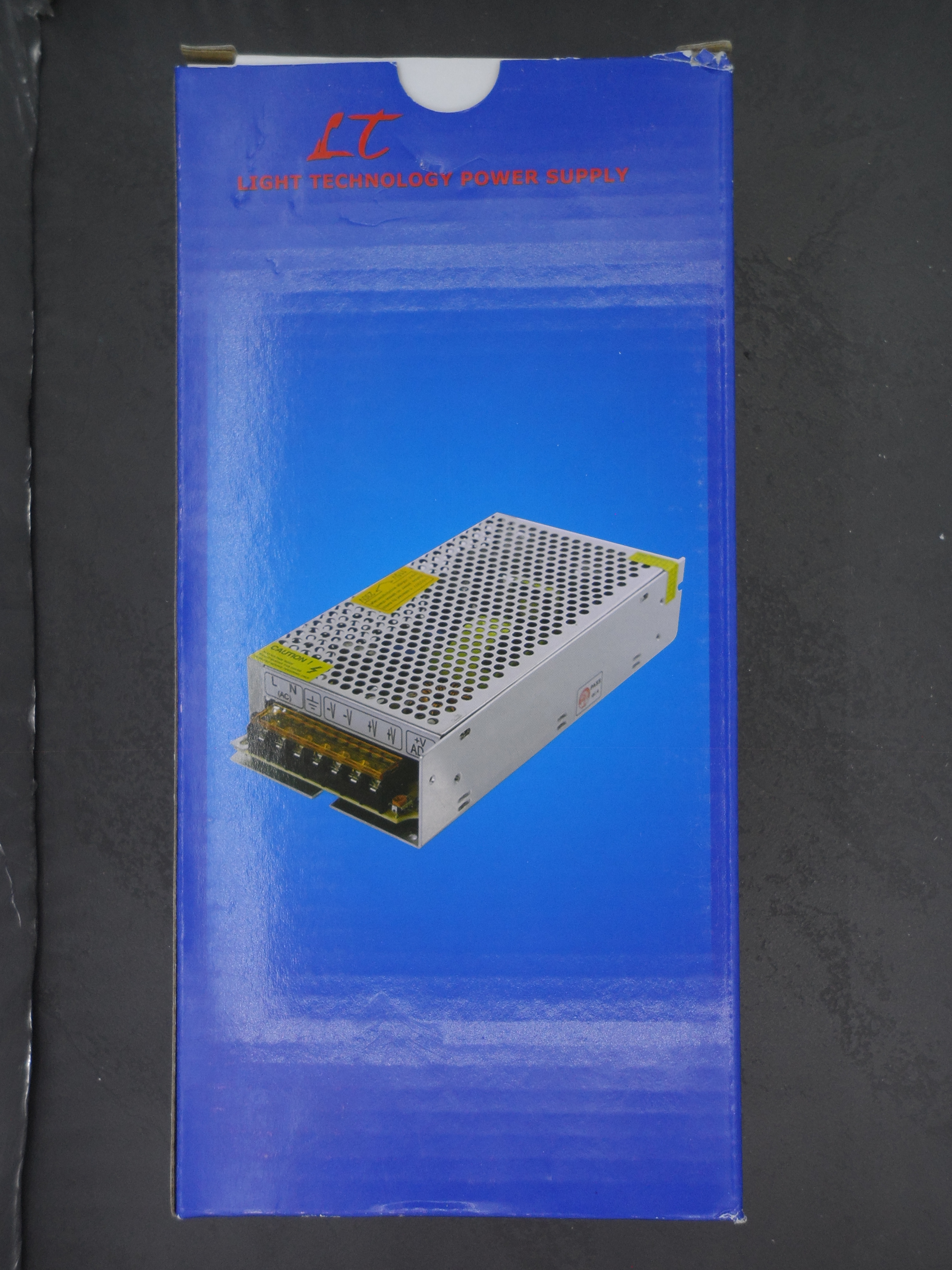
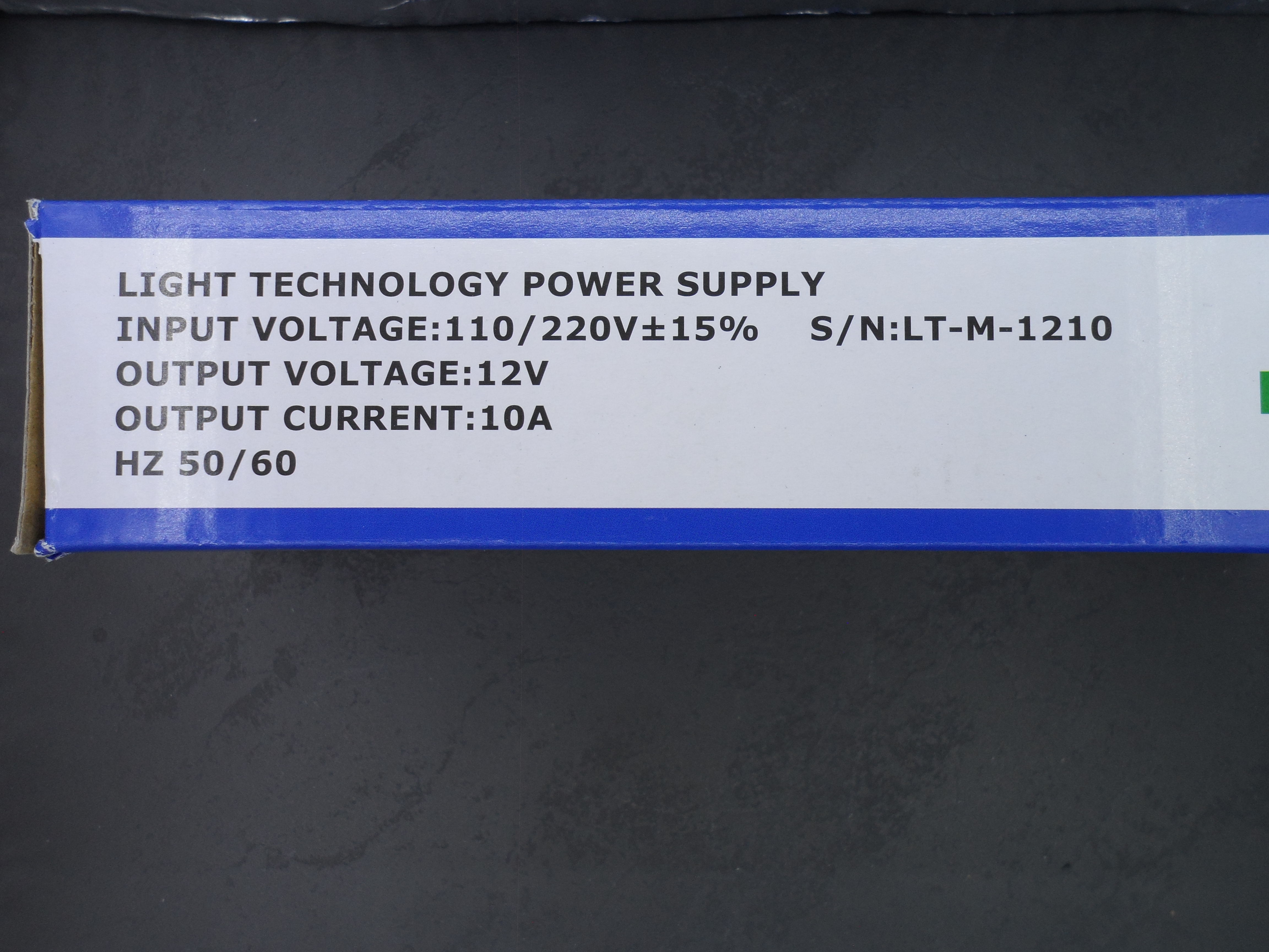
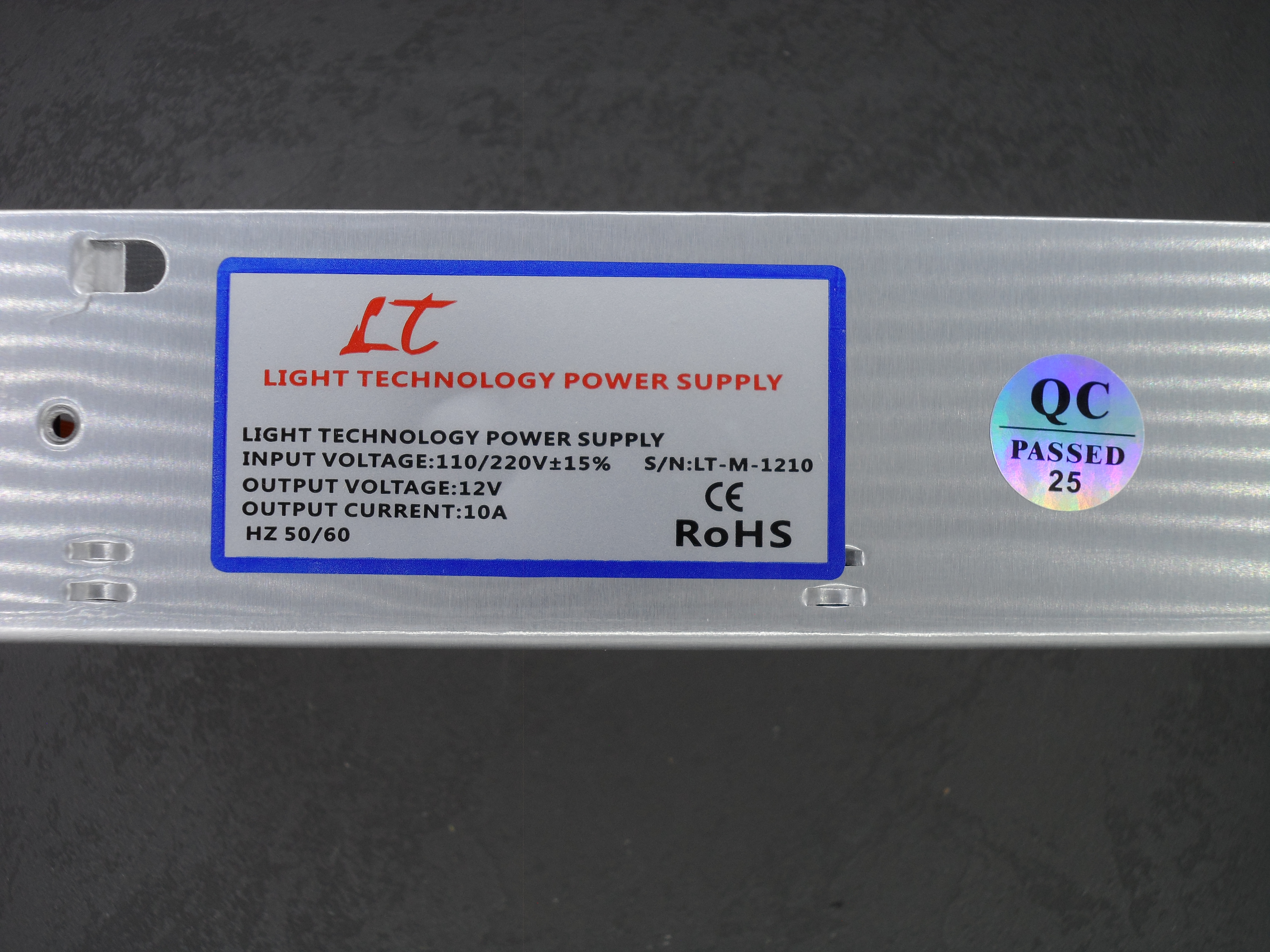
In this post, I will review an LT 12V 10A SMPS. It came in a blue LT packaging with a LT label on it. it’s model is LT-M-1210.
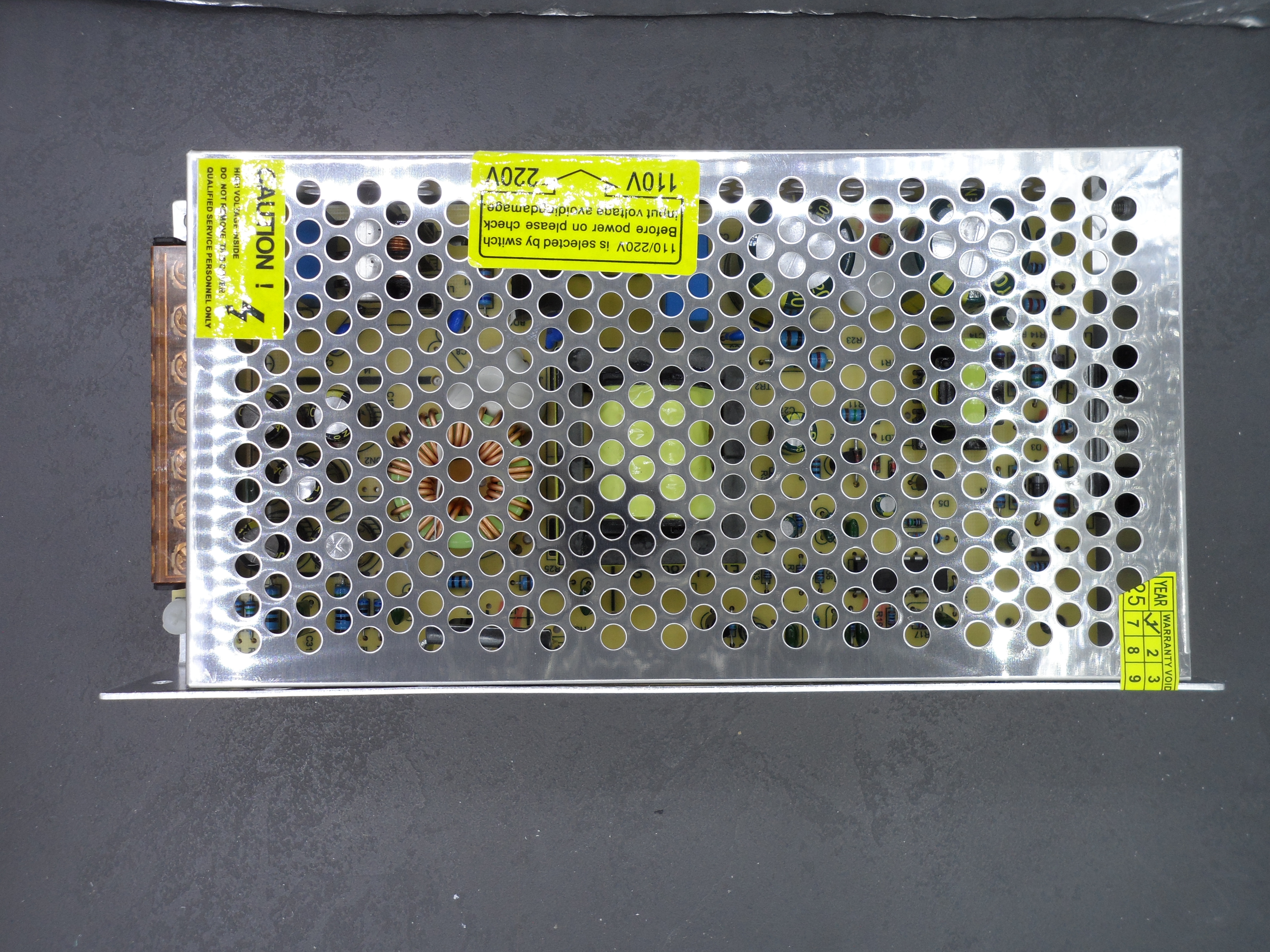
Here is inside of it:
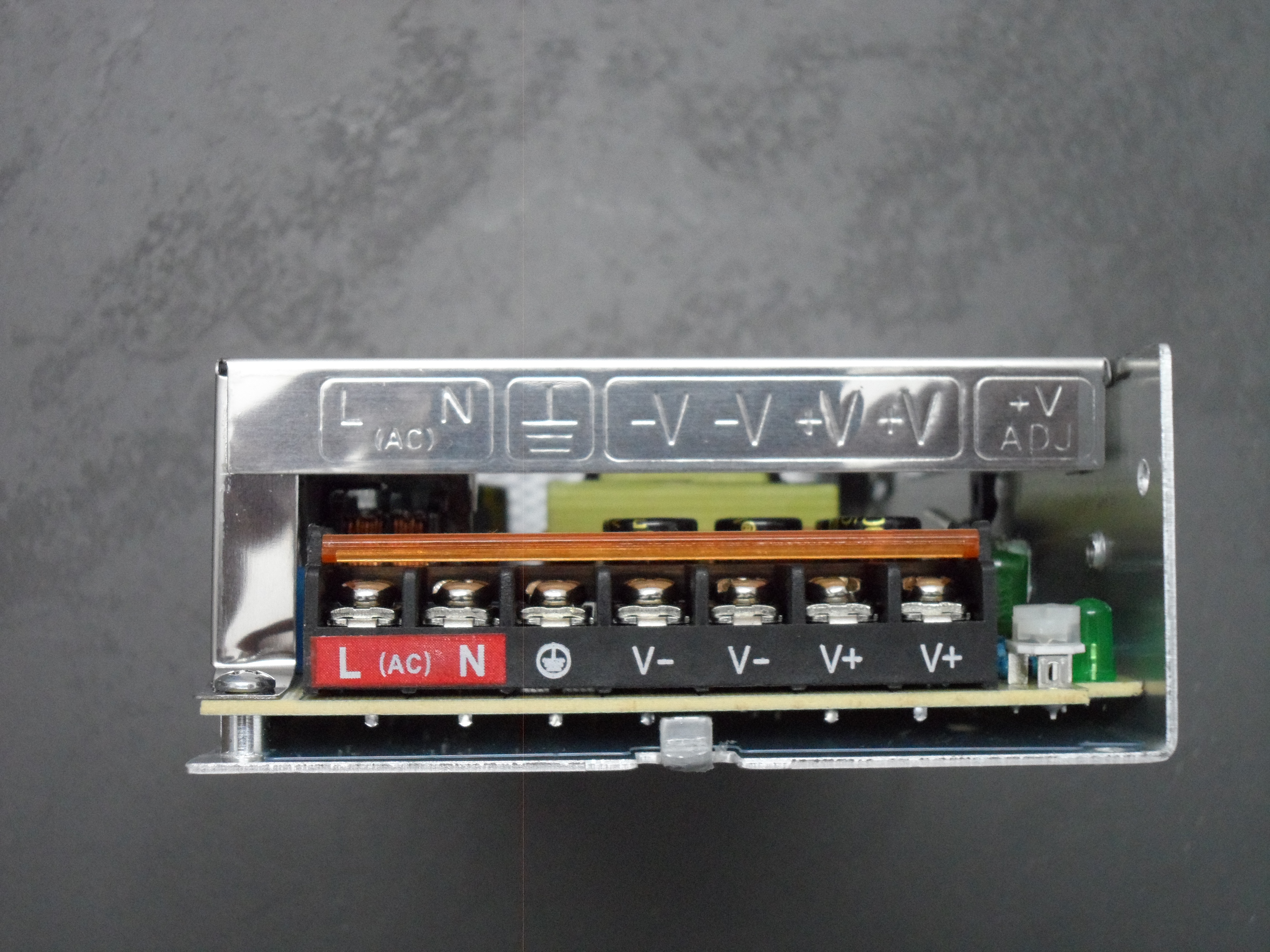
Note that in addition to stamped terminal’s guide on the housing, they even printed on the terminal block itself. This has a additional cost. (I will tell more about it at the end of this post)
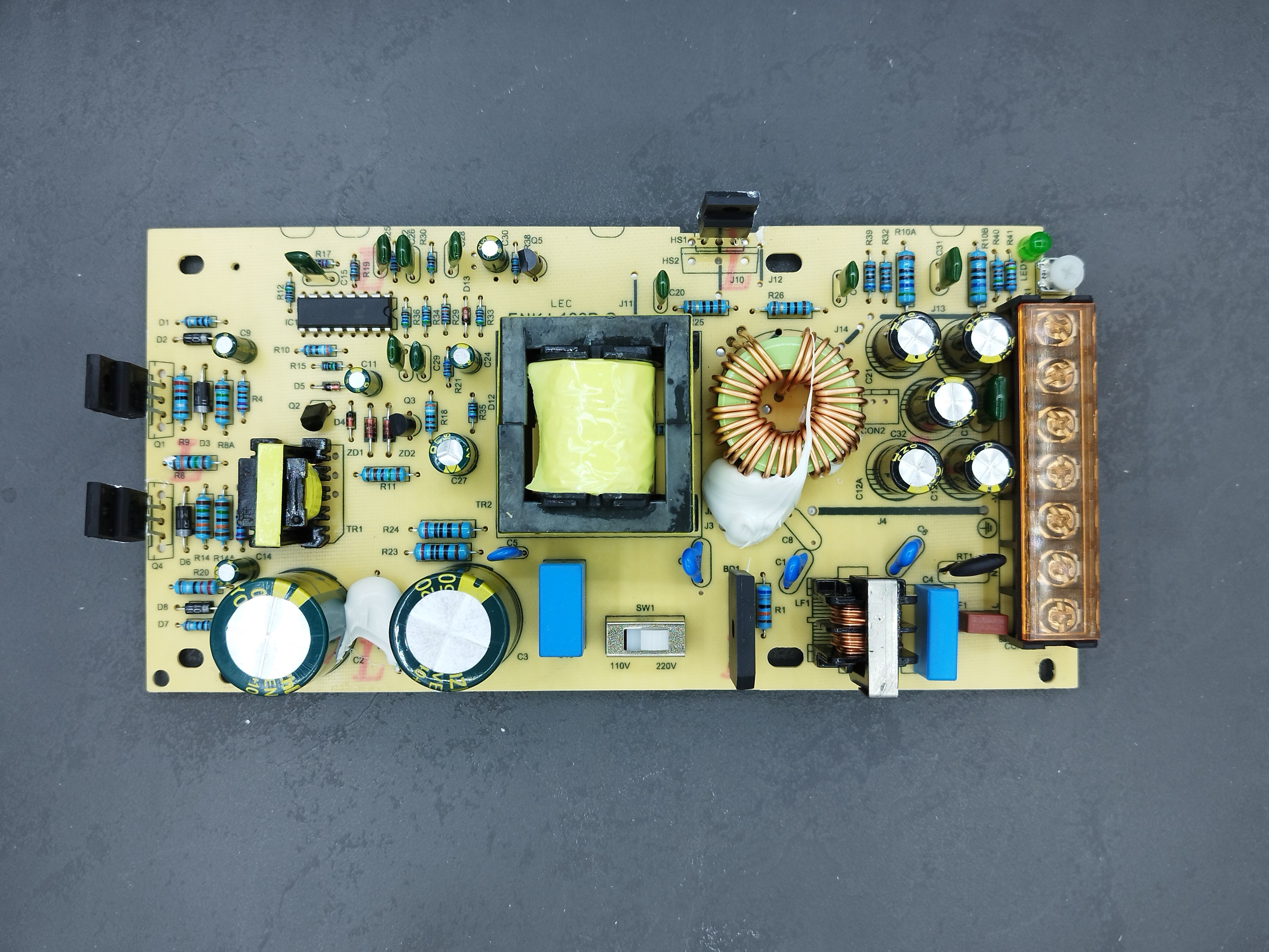
They used the 7500BD for main IC and two MJE13007 Transistors. This topology is a half-bridge, and it is very common to use this topology beyond 120W of output. The flyback topology is used in 100 or 120W power supplies. This Half-Bridge design with its main IC was very common in old ATX computer power supplies. They are made in billions and are reliable and easy to make. The KA7500, or TL494, PWM Controller was first introduced in the 80s by Texas Instruments, and later Fairchild introduced its own KA7500. So this Controller, with those transistors, is available everywhere and very cheap. I think this is why the designer used this topology instead of FlyBack for this power output.
Note that with these new GaN (Gallium Nitride) MOSFETs, which have very low power loss, you can still see flyback designs in 120W and 140W phone chargers.
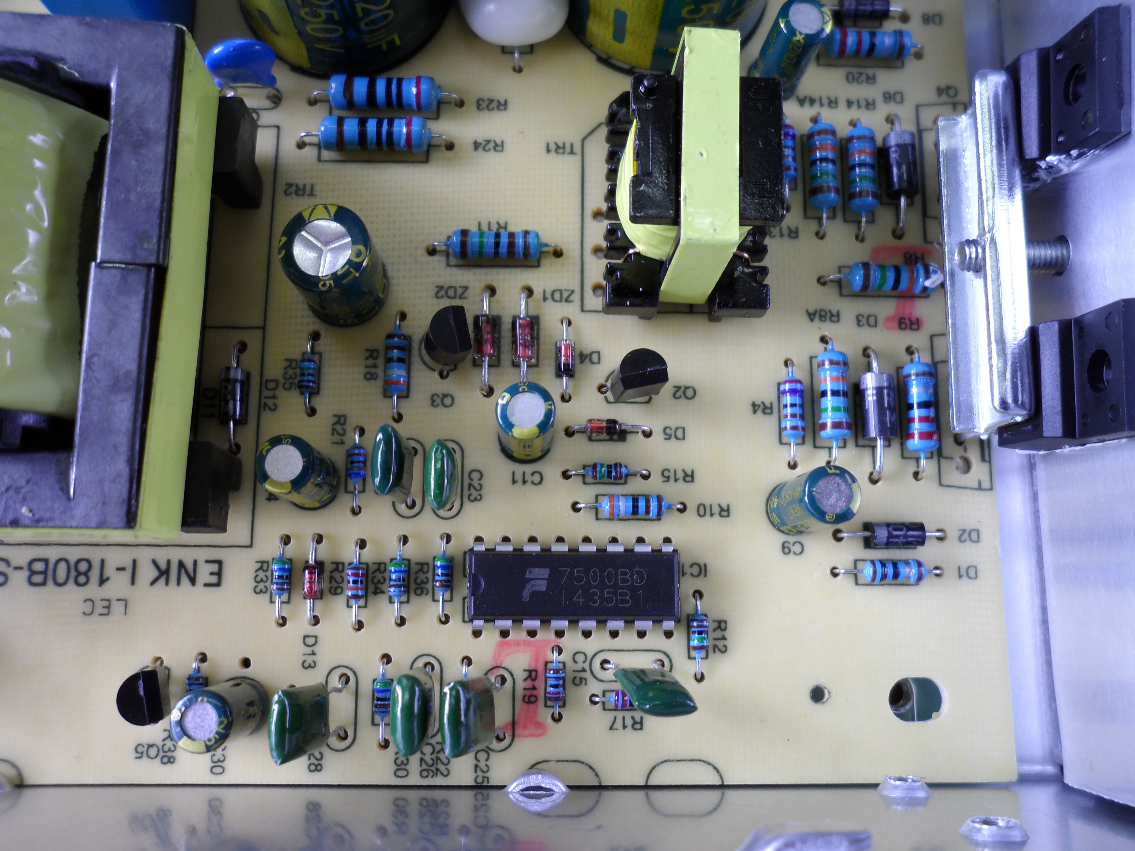
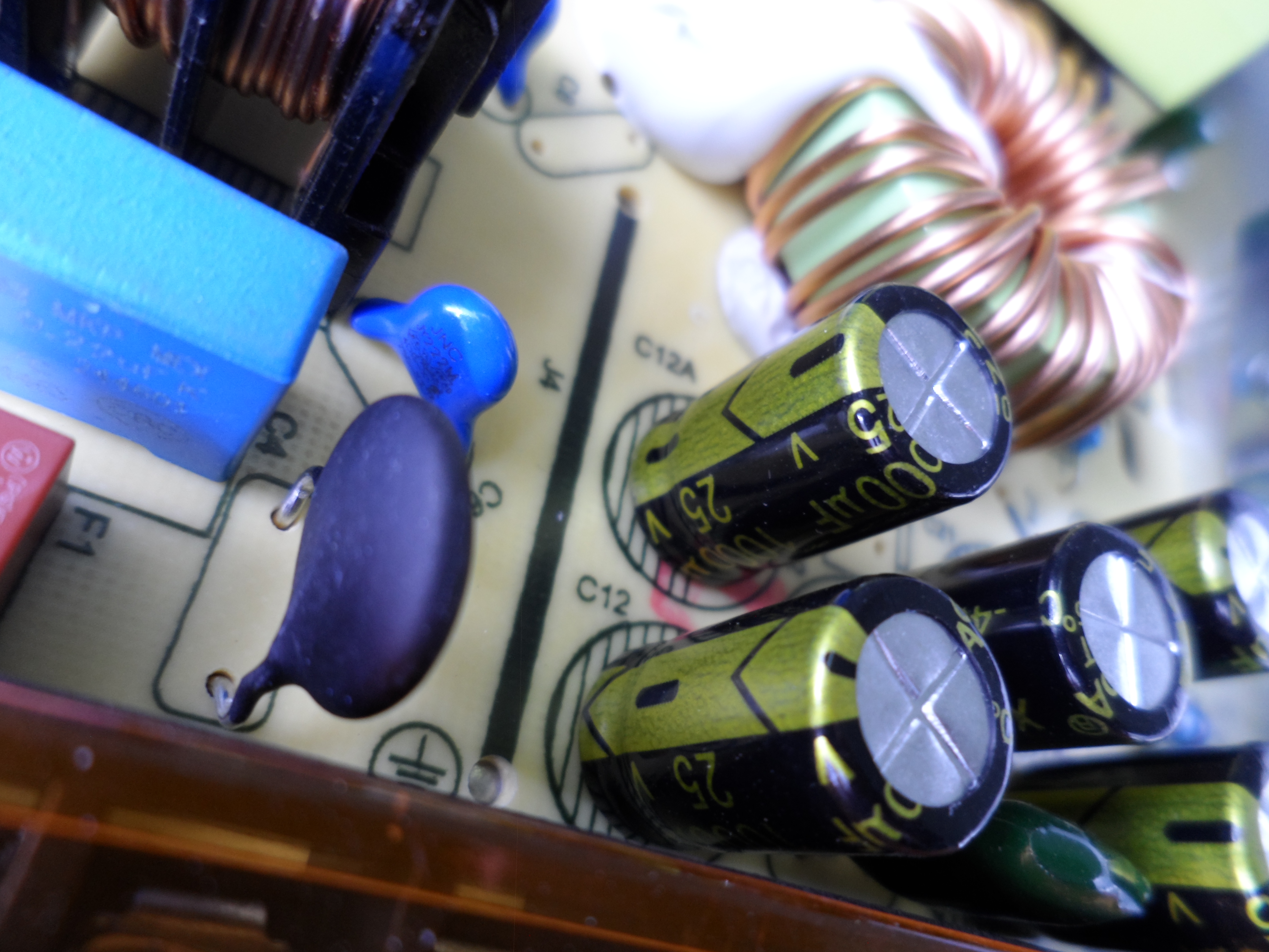
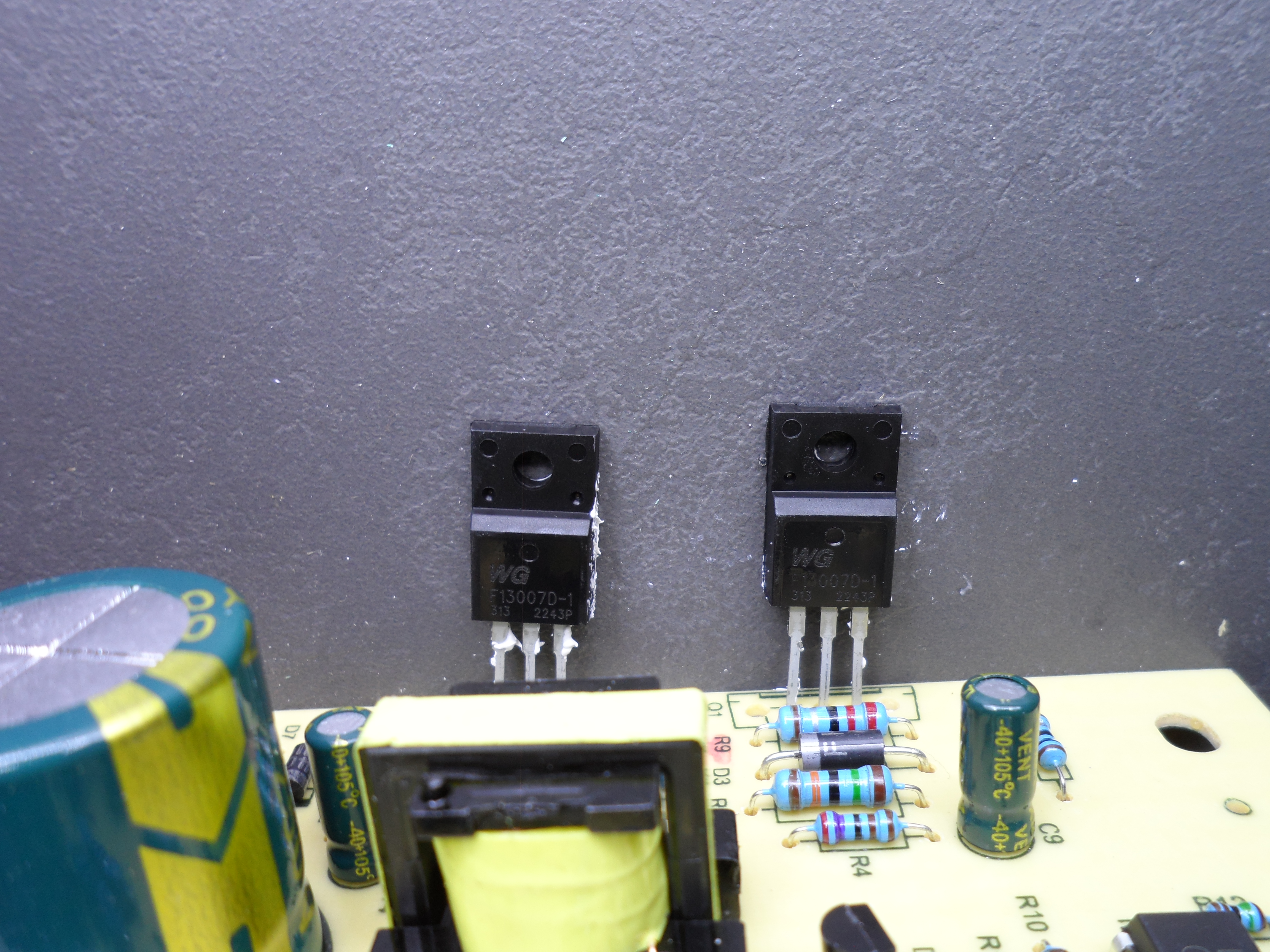
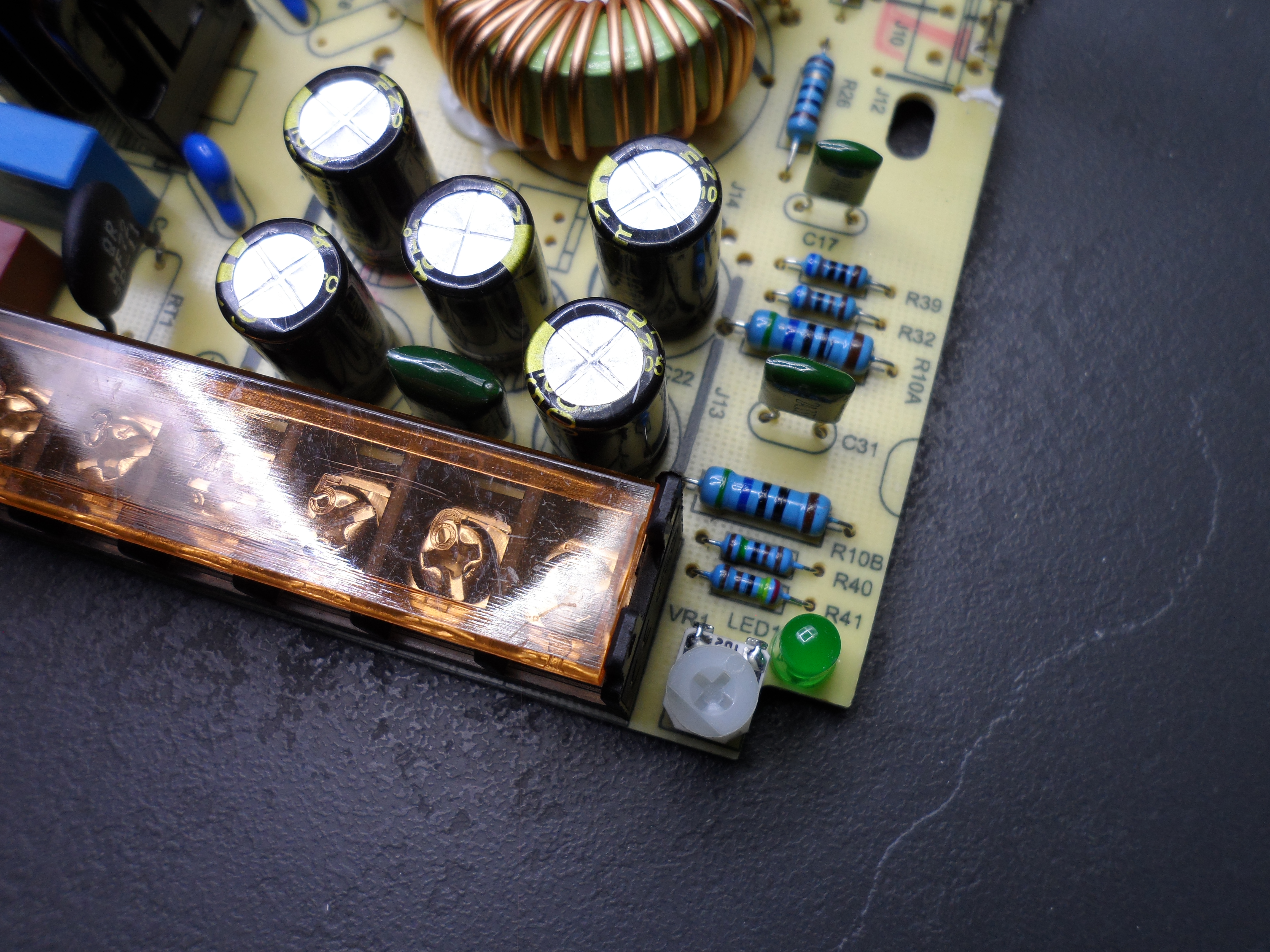
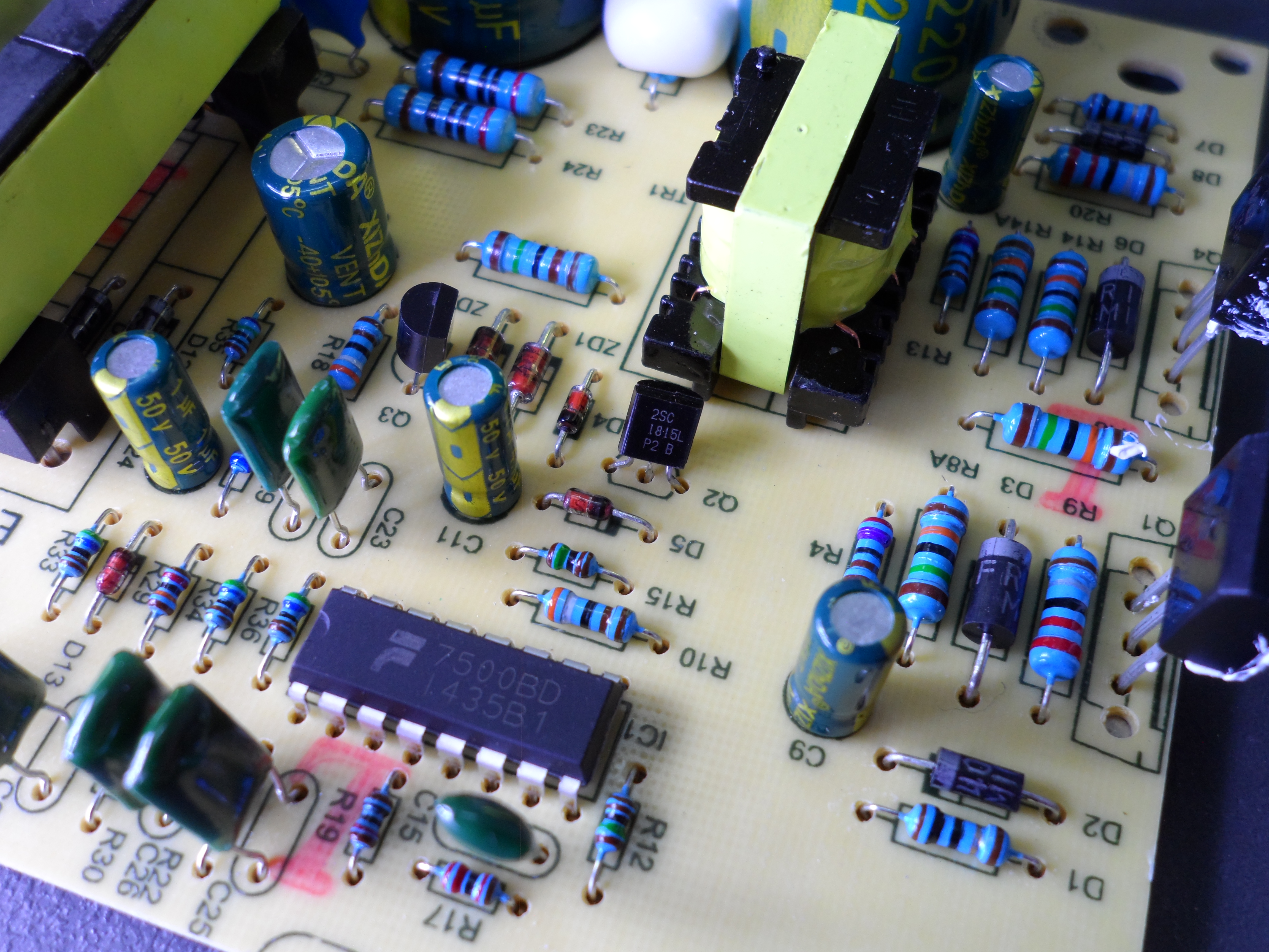
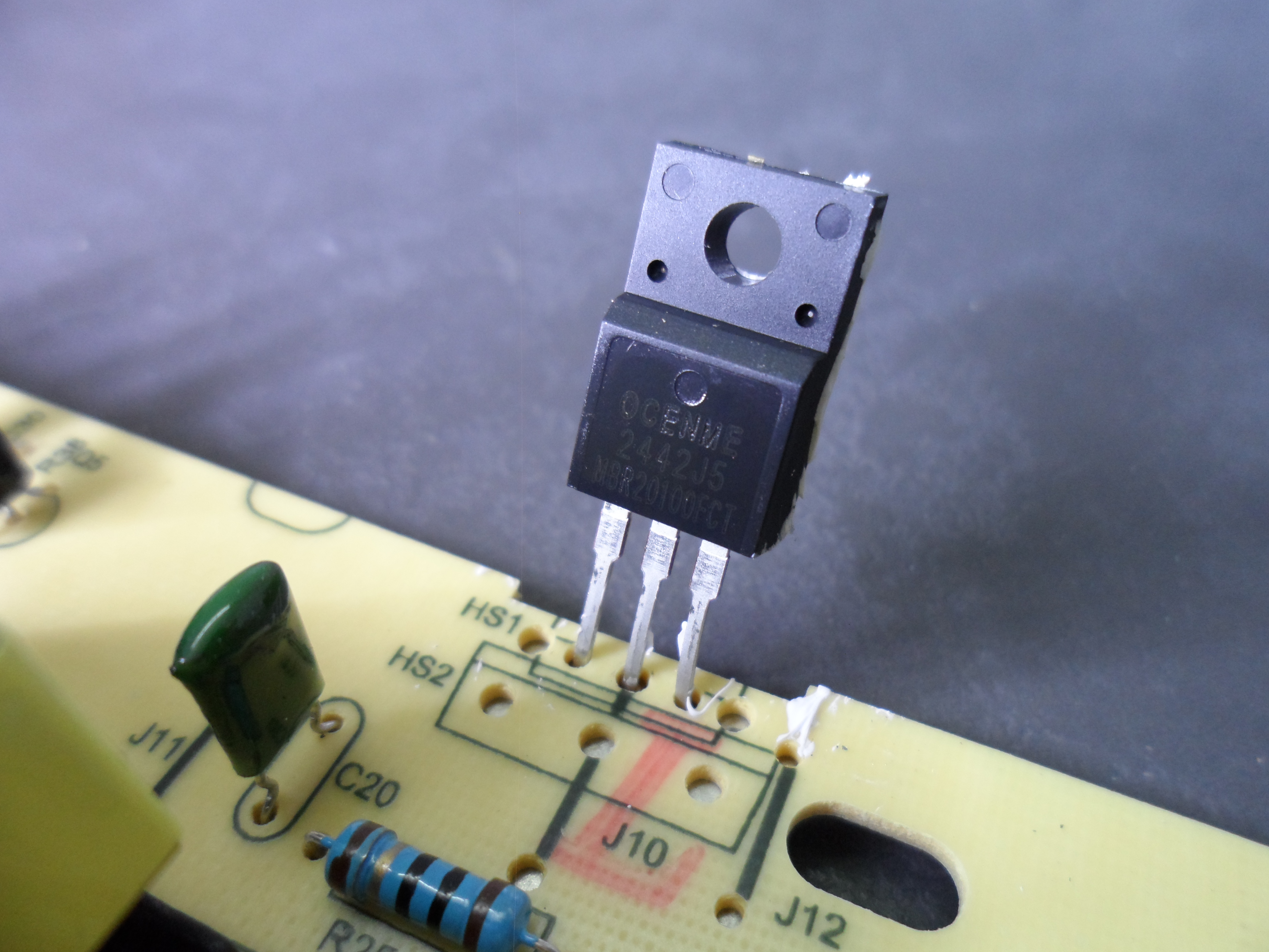
Unlike the fake Tesla i reviewed before, It appears that the transistors are new. output double diode is an MBR20100 Schottky diode; it appears to be new. As everything else suggests, I think the KA7500 is fake or recycled, too.
Capacitors and chokes are placed between Phase and Neutral to filter differential-mode noise. These caps must be X1 or X2 classes, so when the caps fail, they become short-circuited, causing the device fuse to blow.
To filter common-mode noise between Phase-to-Earth and Neutral-to-Earth, additional capacitors are placed. They must be in Y1 or Y2 classes, so when the caps fail, they must not short-circuit, causing the phase to connect to earth, which is connected to the housing. Y1 has better isolation than Y2. In this case, those caps are seems to be real as they have UL and VDE Standards marking on them.
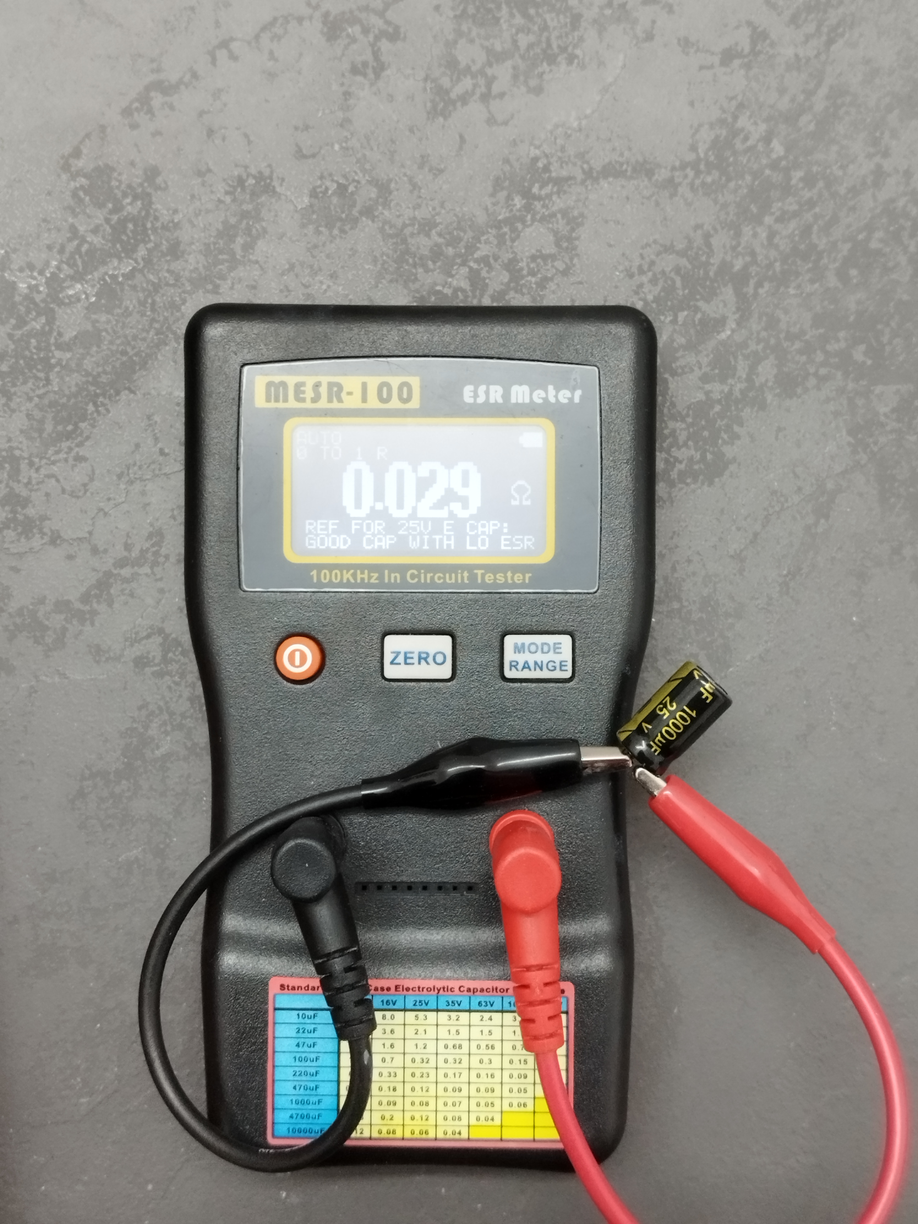
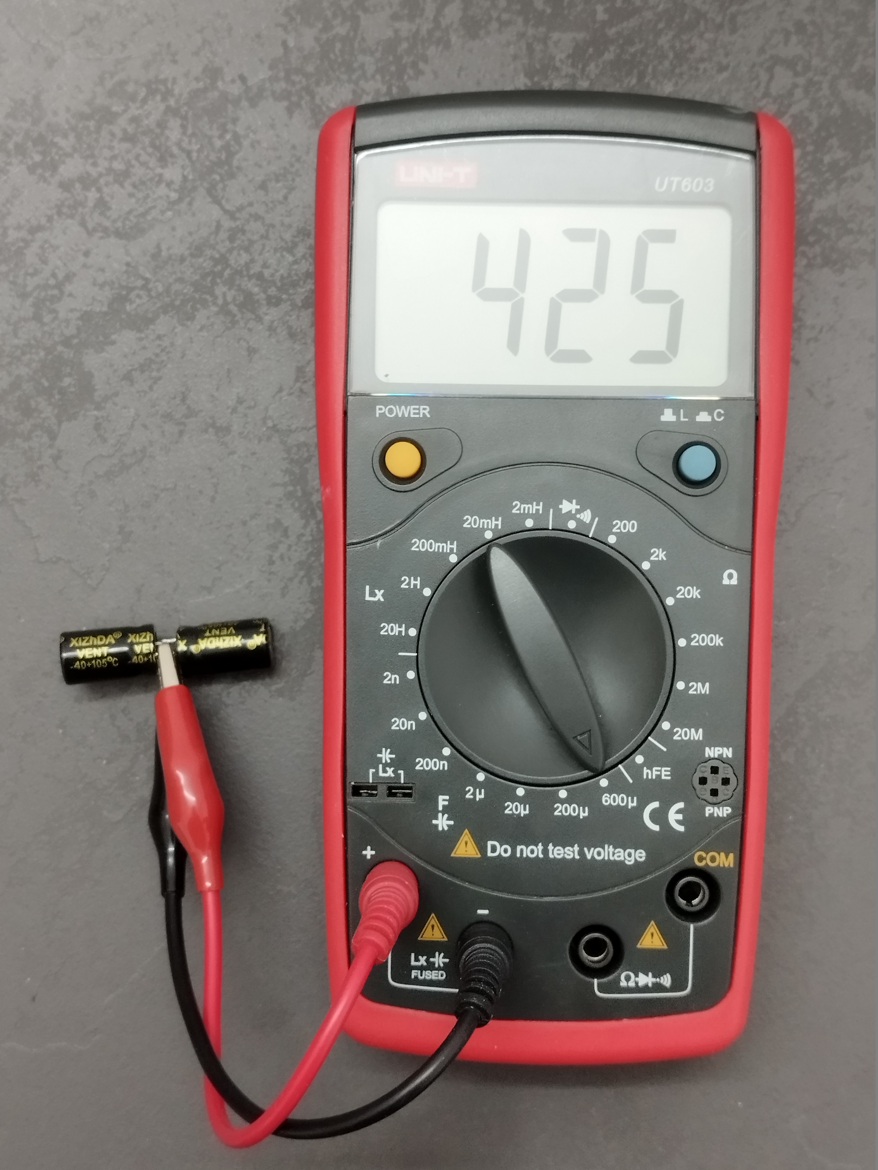
Output caps are 25V 1000uF, and they parallel four of them to become a 25V 4000uF. Since the device has a potentiometer that can adjust the output voltage from 10.5 to 14.5V, 25V capacitors are ideal for this device, Unlike the Tesla one. I measured the Capacitance of one of them, which was 850uF, and the ESR (Equivalent Series Resistance) was 0.029 ohm. This ESR is very close to the same type of high-quality Panasonic capacitor. You may think this cap is high quality too, but very soon, after a few months, the ESR will spike up; in the Panasonic one, this will not happen.
Note that my LCR meter couldn’t measure more than 600uF, so I put two of them in series; the actual capacitance is twice the measured value.
Since I didn’t have a scope, I couldn’t measure the output voltage ripple.
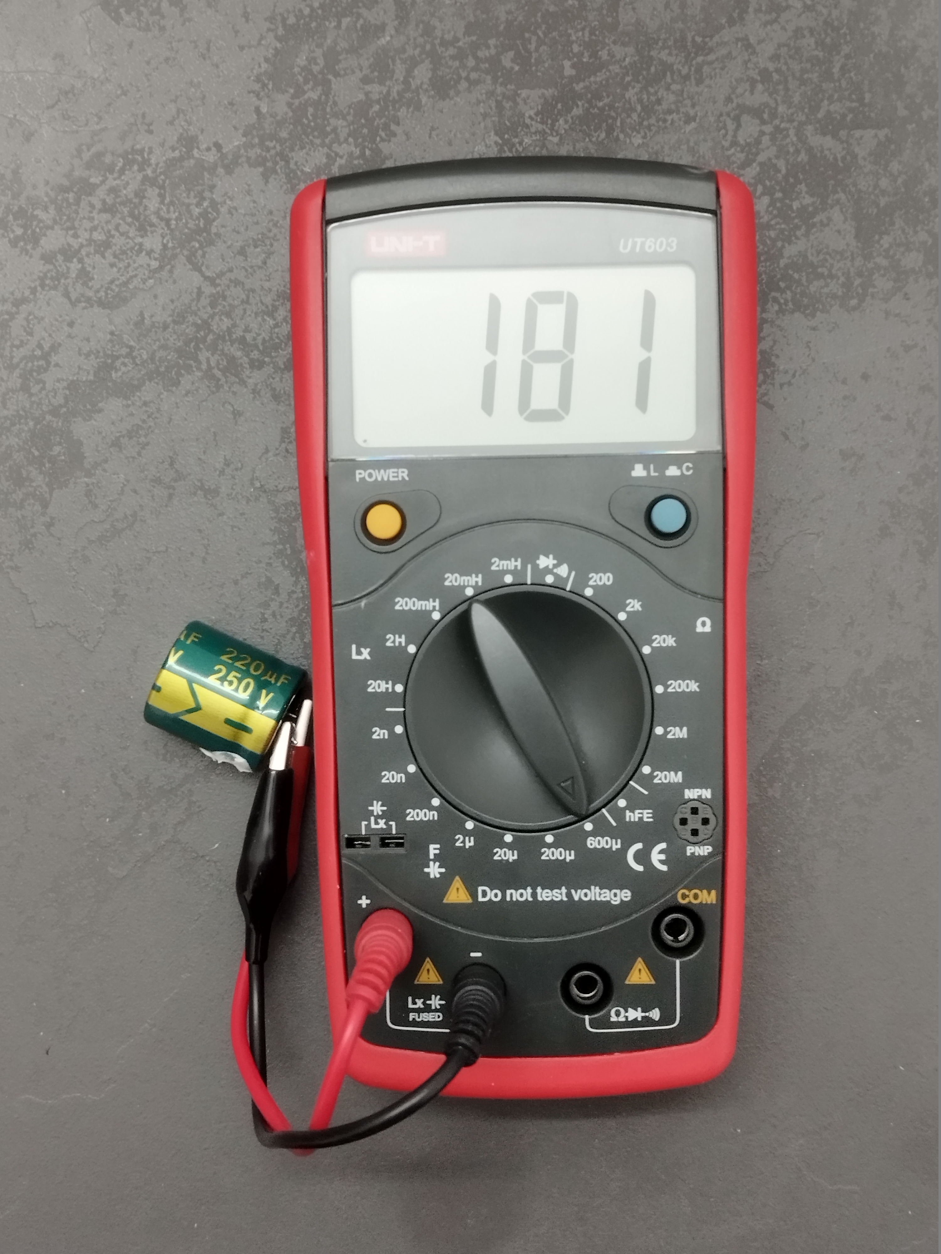
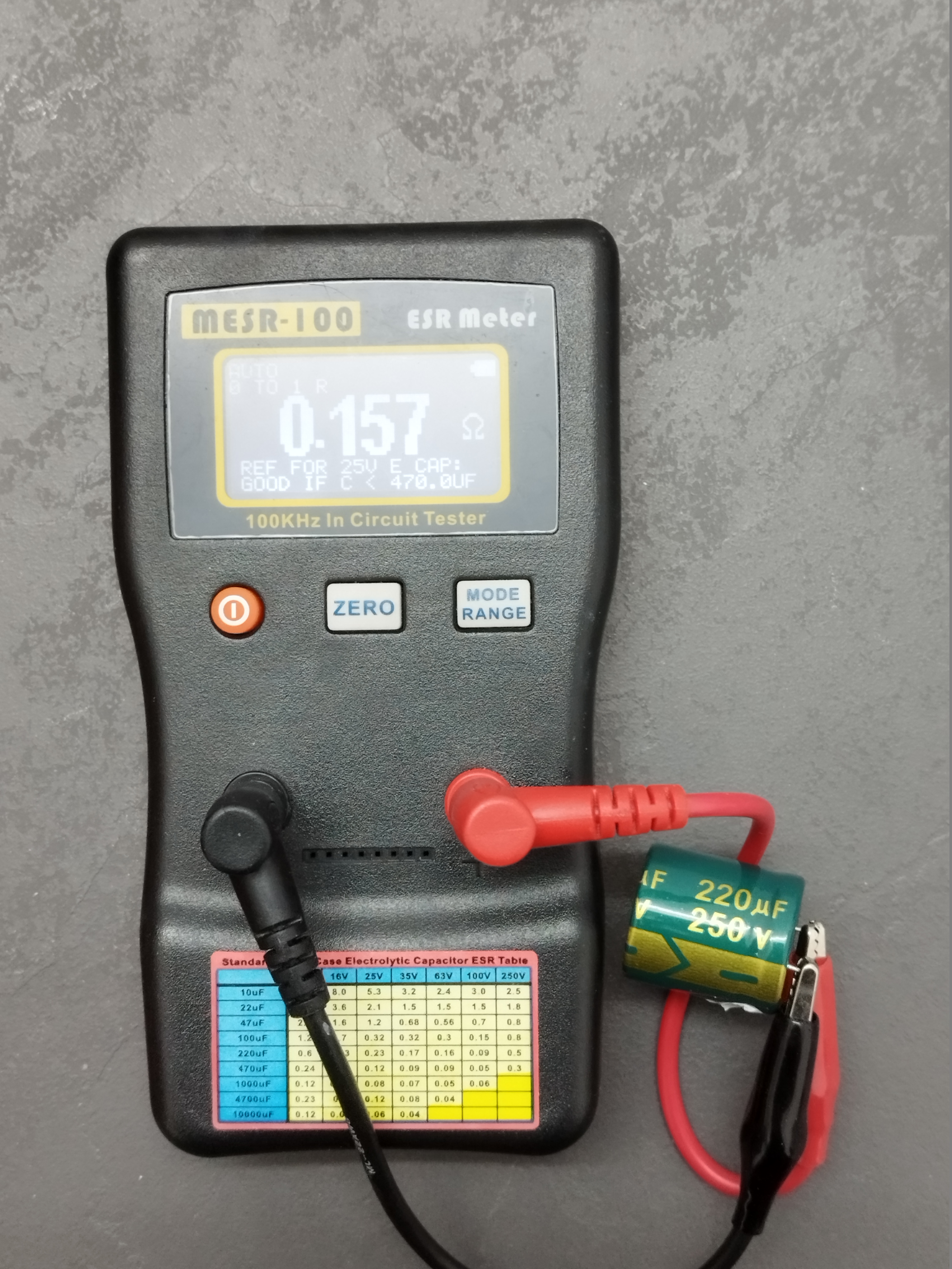
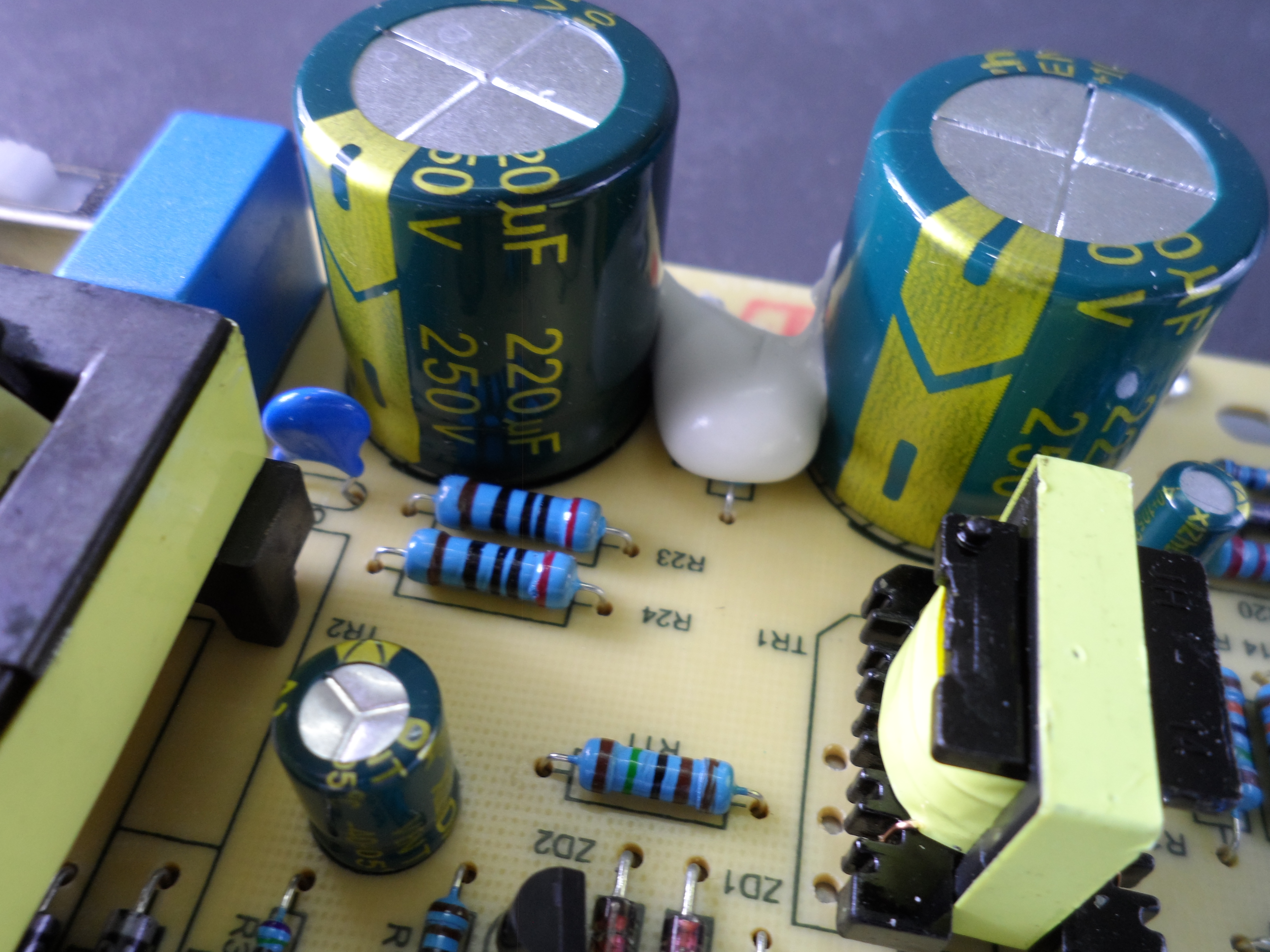
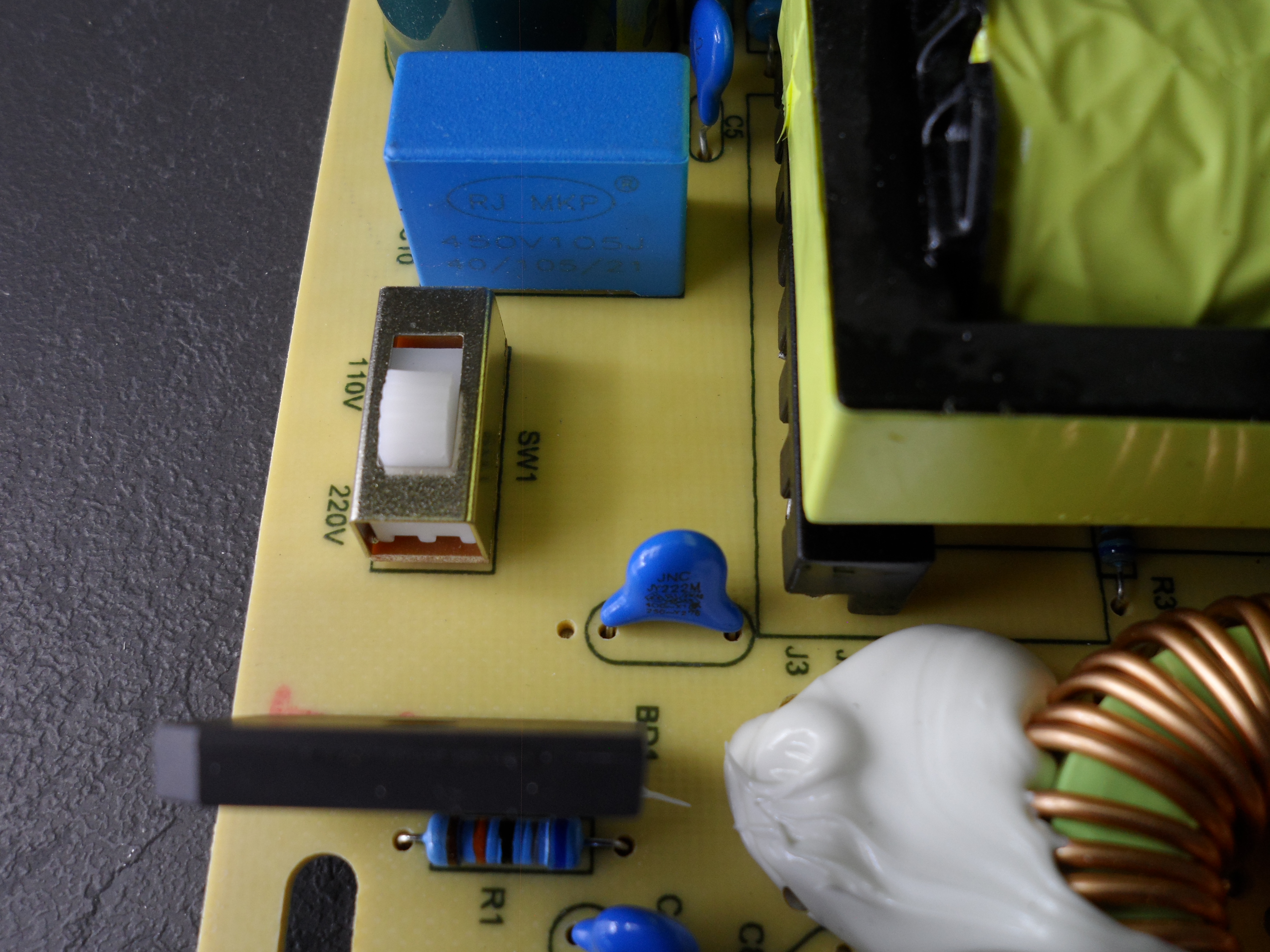
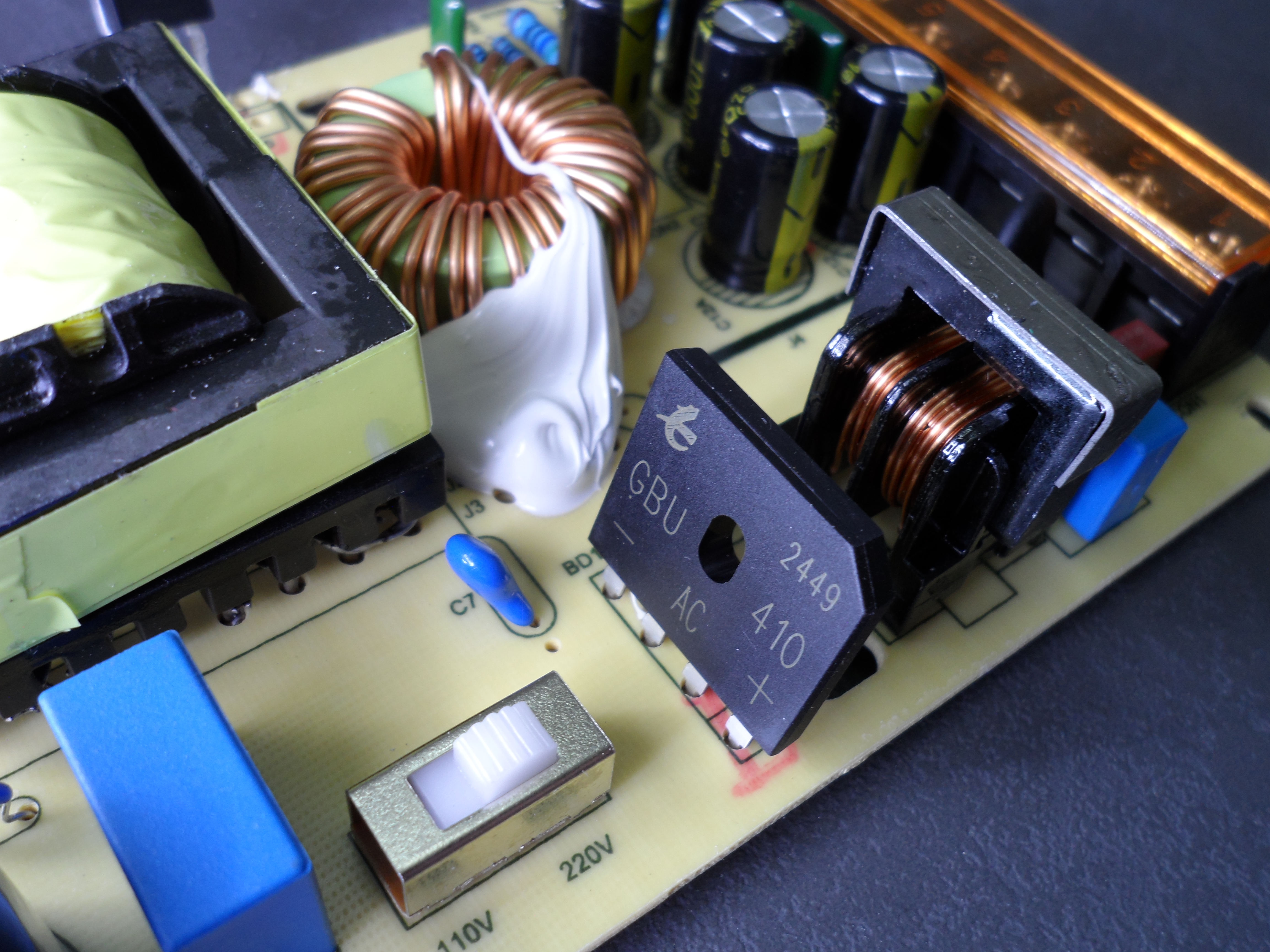
The two input capacitors are 250V, 220uF each. It is recommended that 1uF be used for every watt of output. As the output is 120W (12V*10A), 120uF is very on the edge and it is recommended to use bigger capacitors. I measured them, and they were in the range of 181uF. Note that the device has a switch for 220V or 120V Input, depending on your country’s AC voltage. With that slider switch set to 230V, these caps are in series, so the actual value is 90uF. not even close to 120uF.
In the end, I can conclude that the power supply is slightly better than the fake Tesla. It has 25V capacitors. It appears to have new MJE13007 transistors and better packaging. However, its input capacitors aren’t ideal and could be improved.
In terms of manufacturing cost, the Chinese can deliver anything from an excellent product to a poor product; it depends on the buyer. In third-world countries, many merchants want to lower product prices because many people can’t afford high-quality products. As a result, they use 16V caps, recycled transistors, and a white box without any label. In this case, LT is not ideal, but it is better than the fake Tesla.